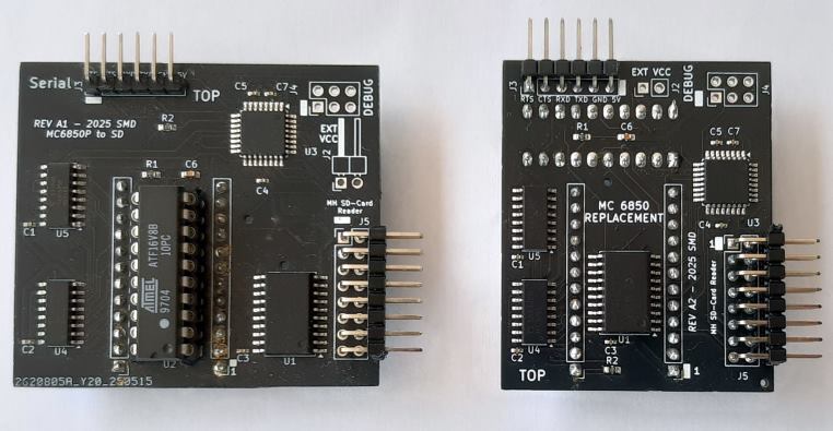
SD card interface (SMD version)
  (user friendly)
SD card interface (SMD version) (user friendly)
|
|
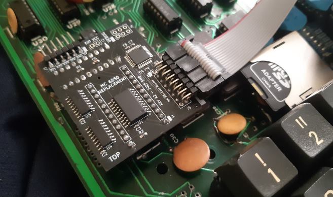
SB600/C1P/UK101 adding an SD card option
BOM
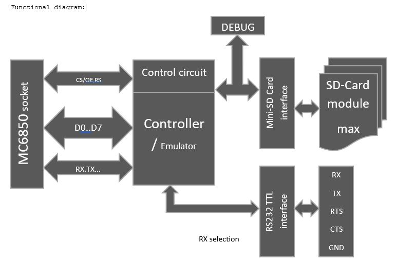
INTERFACE
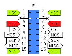
SD CARD INTERFACE (OPTIONAL USB-RS232 TTL ADAPTER):
To connect the SD card module with the above SD card interface, it can be directly soldred to the module, or use a 16pin IDC ribbon cable. Take care for Pin1 orientation ! A cable has the advantage that the SD-card slot can be placed in the computer case, where needed.
ACIA Emulation, how it works:
The ACIA emulator provides beside standard ACIA functions an additional extended function set. The extended ACIA Command register is activated by the control bits CR5,CR6 = 11 followed by a conventional Data out value. Extended commands are grouped into 16 main groups (upper 4 bits). Within each group, 16 sub functions can be selected (lower 4 bits). In total, 256 extended ACIA functions are possible. Extended group (high nibble) - Extended sub function number (low nibble)
If auto-ACIA pre-set is enabled, EEPROM specified parameters (Baudrate, bits,RTS,CTS ) will be used to initialize the ACIA on power up.
Hardware serial output/Input of data is not active during special function mode ! Note: If operation was successful,
in some funtions 0x01
is returned, on Error a value of zero is returned.
Master
reset with $03 is not needed
(only once on machine power on) Example: Extended command byte $07 will call extended group 0 and extended function 7 (`= Set FIFO to 8, no return value). The sequence is as follow: Write for example $71 the ACIA control register followed by $07 that has to be send by a standard serial data output subroutine to the ACIA data register (like when sending data to the serial output). Important: Have a closer look the the SD-Card Reference manual and the code examples form the BASIC extension and Menu program. All SD-card functions are includes in the Revision 2.03 of the W_Osi emultor. Source code and manuals are included in the OSI.SD file, which is an ZIP file and can be opened with any ZIP file program. Extended commands: After sending an extended command, data has to be send in addition or received from the ACIA data port, depending on the function requirements. Reading or sending data is done by standard serial input and output routines. In
case a byte/word/string is send or returned, the user program "must"
handle these or the ACIA
will perform a timeout reset after 2 seconds, which may lock up the user program. If
a status byte is returned, typically a "1" means no error
and a
"0" means the operation failed. Note: "no return" mentiond below means the ACIA will not return a status or any data byte. Most of the extended commands can be interrupted by a reset (0x03) to the ACIA control register (f.eg. reading a file, etc.). I such a case, no command return value will be presented. The function called will be aborted but processed data may remain. Check the function description, if a commands can be interrupted.
Group 0 Set/Clear special functions 0: do nothing 1: return version info return, return 1 data byte 2: reset all special functions, no return value 3: select RS232 internal port, no return (uses system RX/TX lines) 4: select RS232 external port, no return (uses onboard pin header RX/TX lines) 5: Set FIFO to 2 , no return (RTS/CTS handshake by user) 6: Set FIFO to 4 , no return (RTS/CTS handshake by user) 7: Set FIFO to 8 , no return (RTS/CTS handshake by user) 8: Set FIFO to 16 , no return (provides automatic RTS/CTS handshake) 9: read 1 byte from EEPROM, send startL, startH, return 1 data byte (Adr. 0 to 1023) 10: write 1 bytes to EEPROM, send startL, startH, data, return 1 status byte (control) 11: activate(1)/deactivate(0) setup on Boot from EEPROM parameter table, no return 12: write setup to EEPROM, return 1 status byte 13: activate(1)/deactivate(0) RTS for incoming serial data, no return 14: undefined, no return 15: Get last SD Error, returns 1 data byte
Group 1 Execute Loader Code in binary with leading length and start address, no return value 0: Pre-Loader (0240) to load BOOT.SYS from SD, return 65V file for OSI monitor loader 1 to 15: ignored, more code may be placed into ATMEGA in future releases
Group 2 Select baud rate, no return value (SW=software defined, HW=by ACIA TX clocks The ACIA emulator is connected to the TX/RX lines of the ACIA socket. The TX line is alow available on a separate external 5V TTL serial connector with RTS and CTS functionality. The RX line can be software selected to come from the ACIA socket or from the external 5V TTL serial connector. Note: HW
are the only baud rates supported by emulation and TX clock
analysis on startup. The lowest baudrate is 150 and the highest 38400. The 115200 baud rate may work if needed by adjusting the OSCCAL in the emulator core (see function group 4), The reaon is, that the serial deviders and the internal 8Mhz emulator clock do not allow a precise baudrate match on higher baudrates. 0: restore from SW to HW serial baud rate from initial reading of TX clock 1: 150 only SW 2: 300 +HW 3: 600 +HW 4: 1200 +HW 5: 2400 +HW 6: 4800 +HW 7: 9600 +HW 8: 14400 only SW 9: 19200 +HW 10: 38400 +HW 11: 57600 only SW -> transmit works, rest not reliable 12: 76800 only SW -> nonstandard, not tested 13: 115200 only SW -> transmit works, rest not reliable 14: 125000 only SW -> not tested 15: 31250 only SW ->> MIDI IN/OUT, +1.58% faster compared to MIDI
Group 3 SD card functions Note: Only a single file can be opened for R/W. If SD operation holds for more than 2 sec,a soft reset will be initiated to restart the ACIA emulation. So, writing to a file in intervals separated by more than 2 sec will not work! If an operation was successful, a 0x01 is returned, elsewhere a 0x00 Definition: Path text can be max 31 characters long, ending with 0x00. A Path provided should not have a "/" slash at the end or beginning. A Path looks like f.eg. "config/files". File names can be max 23 characters long, ending with 0x00. Upper- or lower-case charters are handled equally. The file extension can be omitted or of any length desired. The first letter in a file extension is used in some cases to identify the type of file. No file extension is treated as an executable binary file. Extensions recognized are: .Bxx for Basic text files, .Pxx for binary executables files with the loading/tart address at the beginning, .Lxx , .6xx and .Hxx are OSI machine code files. Files larger than 64k can be read but not written (max 64k). In the following functions, a file read from the disk by the user must be interpreted and handled accordingly. The BASIC SDLOAD command extension may autoload the file according its extension or to the target address defined by the user. Typical random read speed (with a 32GB card, Im using) is about 12-15 Kbytes/sec compared to the 10 Kbyte/sec for the OSI floppy disk system. 0: start and check SD card (will close all files !), returns 1 if available, 0 if not 1: close and eject SD card, no return (card needs to be re-inserted !) 2: get name of entry number (0..255) as string of selected path, return name zero term. 3: set filename, name ends with byte zero (max 24 characters incl. zero), no return 4: check if file exist, returns 1 status byte 5: set path, ends with byte zero (max 32 characters), no return 6: return directory list, name plus zero. Ends with zero at end of directory. The directory output may be interrupted by sending a break $03 to the control port. Returns no value after a break command. Break must be done at the beginning of the next directory string output. (note: older ACIA firmware may not work correctly) 7: get free disk space in MB, returns 2 data bytes 16bit 8: get file size in bytes, returns 2 da bytes 16bit, returns 65535, if file larger than 65535 bytes (in BASIC -1) or 0 if file does not exist. 9: read file, read 2 bytes file size, returns zero word on error or no file present, followed by binary data. Aborted by writing $03 to ACIA control port if needed, no return. 10: create folder in selected path (folder name in filename) returns 1 status byte 11: delete folder in selected path (folder name in filename), returns 1 status byte 12: delete file (defined before with path), returns 1 status byte 13: rename file or folder, send new filename, name ends with byte zero (max 24 characters), returns 1 status byte. Use function 0x33 to specify file to rename. 14: write file, send 2 bytes file size (max 64k), return 1 status byte, if file was allocated. Next send binary data, may be aborted by writing $03 to ACIA control port. returns 1 status byte when done, nothing on break. 15: copy file, send new path followed by new filename, if path is just zero, the same path is used as the source. Filename and path must end with byte zero (max 24 characters for filename and 32 characters for path), returns 1 status byte. Use function 0x33 and 0x35 before, to specify source file. Note: before rename, do step 3,5 and 4, to define file to be renamed!
Group 4: IRQ enable/disable timer, does not set IRQ flag in Status register NOTE: activates even if IRQ enable is not set, IRQ signal resets after 10µsec by itself NOTE: CTS can be used as an interrupt input and disables normal CTS behavior 0: disable timer IRQ 1: IRQ on CTS goes low. IRQ resets after 14µsec by itself 2: IRQ 128 µsec 3: IRQ 256 µsec 4: IRQ 512 µsec 5: IRQ 1.024 msec 6: IRQ 2.048 msec 7: IRQ 4.069msec 8: IRQ 10 msec 9: IRQ 16.67 msec (60 Hz) 10: IRQ 20 msec (50 Hz) 11: IRQ 32.78 msec (max) 12: read OSCCAL factory calibration value, returns 1 byte 13: read actual OSCCAL, returns 1 byte 14: write OSCCAL, changing will lead to non-function TX/RX baud rates !! 15: reset OSCCAL to calibration value Note: to use IRQ on OSI bards, you have to connect pin 7 (Socket of ACIA) with the CPU IRQ line Pin 4. On other systems, this might be already connected. OSCAL allows variation of system clock in a range of +/- 25%, if you need to adjust to special external baud rates. The calibration value should work for standard baud rates but can become helpful on rates > 38400 to fine tune the interface timing if needed.
Group 5: Virtual disk commands The virtual disk is an image of a data disk in a single file. The virtual disk comes with a header to identify that it is a valid image and disk format structure. The standard sectored disk access method is done by addressing a 16bit sector address and read or write max 256 sectors from that position onwards. The alternative track disk access method is done by addressing an 8bit track number, addressing a read or write offset to the start of the track. Then read or write data per track of up to 15bit or 32k without looking for sector limits. 0: Close actual virtual disk, no return (use only for virtual disks) 1: Set actual Virtual disk filename by number (0..3) active, no return. Default names are VDISK_A.DSK...VDISK_D.DSK. Using define filename (function 0x33) afterwards is possible to select any other file name. Use create folder (function 0x3A) before virtual disks are created with function 0x53, if a group of virtual disks should be placed together. 2: define actual virtual disk header (number of sectors per side, sector size, sectors per track per side), 15 bit value, 8 bit value in bits (B7:sides + B6..B5:4 sector size types + B4..B0:32 sectors per track per side),(write protection is always on). Sector size types are:0=128,1=256,2=512,3=1024 bytes per sector at 1..31 sectors per track per side, no return. No data is written onto the file yet; it will be written only by create virtual disk (function 0x53) 3: Create empty virtual disk on SD, no input required. (header 32 bytes)(VIRTUAL ID "ACIADSK", Version, in 8 bytes), (number of sectors, sides, sector size, sectors per track) , 19 times 00). Sectors follow in sequence, second side follows first side sectors (double sides disk have twice the sectors), returns error status 4: Open actual virtual disk with name that was given in function 0x51 or 0x33 before, returns error status. Before selecting any other file, use close virtual disk (function 0x50) and before using any other disk R/W function of the 03x group, because they will close all files after the call. 5: Get actual virtual disk layout (number of sectors per side, sides, sector size, sectors per track per side, number of tracks) returns error status, followed by 15bit value + 8bit value + 8bit value, if no error occurred. 6: Set or Clear actual virtual disk write protection (only during session) 8 bit value, 1=set, 0=clear. elsewhere virtual disks are always write protected by default. No return. 7: Set actual virtual disk position (sector number) 16 bit value (consider single or double side layout), returns error status. see Note Sector logic. 8: Read sectors (number) 8 bit value (max 256 sectors in continuous sectors only form) returns error status. If ready, a one is returned and read transfer of sector data can follow, else termination. No return. 9: Write sectors (number) 8 bit value (max 256 sectors in continuous sectors only form) returns error status. If ready, a one is returned and write transfer of sector data can follow, else termination. May be aborted by writing $03 to ACIA control port. returns 1 status byte when done, nothing on break. 10: Scan if SD card is inserted without closing files, like in function 0x30).returns 1 if SD card is inserted, 0 if not 11: Alternative virtual disk method, Goto track number (8 bit value, 0...255 tracks) and sets track position to the start of track, returns error status. Max 256 tracks on double or single side disk, Side select not needed. See Note 12: Alternative virtual disk method, advance read/write track position 15 bit value in bytes (32k range), returns error status. No return 13: Alternative virtual disk reading, read number of bytes starting from actual track position (15 bit value (32k range), returns error status. If no error, read transfer of byte data can follow, else termination. 14: Alternative virtual disk writing, write data bytes starting from actual track position (15 bit value (32k range), returns error status. If no error, write transfer of byte data can follow, else termination.May be aborted by writing $03 to ACIA control port. returns 1 status byte when done, nothing on break. 15: NDY Note to
7 - Direct sectored virtual disk: max 2 sides Note to
11 (alternative tracked virtual disk): Sector logic: This results in a max alternative virtual disk capacity max 2 sides Example: Double sided disk, 40 track, 8 sectors/track. This would allow you to read 16 sectors from each track (using both sides) without selecting the side during a read/write sequence. Single sided disk, 40 track, 8 sectors/track, (@ side 0). This would allow you to read 8 sectors from each track
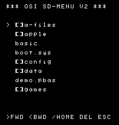
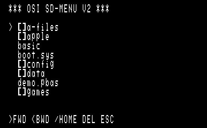
SOFTWARE FOR OPERATION CONFIG.PBAS: MENU:
(can be started form BASIC by the SDRUN command) BOOT.SYS:
(same as the program BASIC) There
are different versions of BOOT.SYS for different memory configurations
like 4k, 8k, 16k, 24k 32k and 40k systems. The reason is, BOOT.SYS
places itself at the TOP of memory and leaves the lower BASIC memory
untouched. Menu
navigation is done by the three keys: ">"
, "<" and "/" on the keyboard Key
"ESC" will go back to BASIC with extended BASIC available. UK101 users: Instead of ESC, you can type Shift-Control-K Note: to use BOOT.SYS on OSI sytems, a cold-start has to be done to initialize ROM BASIC. Recognized file extensions: .PRG and PBAS - This are binary programs with two leading bytes representing the start address (like Commodore software) .BAS - This is the standard BASIC text file from Cassette, like it is generated during a listing .LOD - This is the standard MACHINE CODE text file from Cassette or other machine code programs .HEX and .65V - same as LOD In
addition, BASIC programs can come in form of a .PRG file named
*.PBAS. These
Basic files have a special header to allow the BASIC program
to be stored in Binary format. It speeds up program loading
by more than a factor of 10. To store BASIC programs in .PRG
format, you can use my Emulator and save your program under
Load/Save Binary in the file menu. New BASIC commands:
BASIC commands only available on 16k RAM or more:
HARDWARE AVAILABILITY If you are interested, please send me a note to my E-mail address shown below.
|
|
Schematics |
|
![]()
Last Update: April 2026
 SD card inteface
 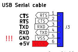 RS232 TTL / USB interface
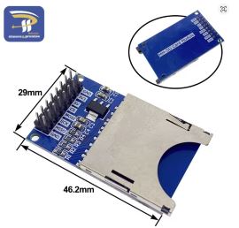 full size SD card interface
 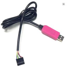 6-Pin PL2303HXD